Introduction
This tutorial adds to the previous one, in which we wrote a sketch for a Wemos D1 mini (ESP8266) board, to read out and print accelerometer data. Now, we want to publish this data to an MQTT broker in the local network via WiFi.
Prerequisites
For this tutorial, we will switch to PlatformIO. Also, you should be familiar with how we interfaced the sensor in the previous tutorial.
Idea
We will outline the steps on how this should work:
1.) On powerup, we initialize the accelerometer and connect to a hardcoded WiFi network (in the future, we can modify this to allow dynamic configuration of the desired network).
2.) When the WiFi connection is ready, we set up a connection to the MQTT broker.
3.) Very important: We have to think about how we deal with connection loss. For this reason, we add two callback functions: One that is triggered when the connection to the MQTT broker is lost, and another one that is triggered when the connection to the WiFi network is lost. In both cases, we stop the interrupt that notifies us about new accelerometer data and keep trying to re-establish the connection regularly.
4.) Once both connections (WiFi and MQTT) are ready, we enable the interrupt from the sensor.
5.) The interrupt routine from the sensor just sets a flag that new data is available. In the main loop we will then check this flag and fetch the data from the sensor when necessary.
6.) When we have fetched a new set of data from the sensor, we will publish this on a defined MQTT topic. Since we have 3 values to publish (x, y and z-axis), there are multiple ways to approach this:
- a) We publish the values as a JSON string {‘x’: 0.001, ‘y’: -0.21, ‘z’: 9.81}
- b) We publish on three different topics (/accel/x, /accel/y, and /accel/z)
Since option b has a lot of overhead (on publisher side we need to send to three topics, and on the subscriber side we need to subscribe to three topics), we choose option a.
Step 1: Install the required library
Since we don’t want to write all the socket stuff that comes along with MQTT ourselves, we use a well-known and popular library for connecting to MQTT. It is called Async MQTT client from Marvin Roger, you can find the GitHub here.
Install it in PlatformIO by going to Home –> Libraries and under the “Registry” tab, type “asyncmqttclient” into the search field. Click on the one where it says “by Marvin ROGER” and click on the blue “Install” button. Do NOT use the one where it says “esphome”.
Step 2: The code
Here you can find the complete sketch for achieving the desired feature described above. Note that you have to adjust some variables to your environment:
- Set the WiFi name and password to the correct values for your network
- Set the address or domain name of your MQTT broker, as well as port, username and password
- Set the MQTT topic to the one you would like to use.
- Set the hostname to the one that should be used for registering at the broker.
The code will publish accelerometer data on the topic <hostname>/accel with QoS 0 (Almost once), to avoid any overhead regarding duplicate packet detection. Similar to a UDP packet transmission, we want to have the least overhead possible for transmitting the data, since it arrives in 10Hz intervals. (Well of course, the JSON string creation produces a lot of overhead, but we do it this way for simplicity).
Also, for simplicity I put all code in one single file. Paste the following code into src/main.cpp:
#include <Arduino.h>
#include <ESP8266WiFi.h>
#include <MPU9250.h>
#include <AsyncMqttClient.h>
#include <Ticker.h>
#include <string>

#define DEBUG  // Enable debug messages

// Sensor-related declarations
#define MPU9250_CS_PIN  16  // Chip select is on pin 16 (Wemos D1 mini: D0)
#define MPU9250_INT_PIN digitalPinToInterrupt(5)  // Interrupt is on pin 0 (Wemos D1 mini: D1)

// An MPU9250 object with the MPU-9250 sensor on SPI bus 0
MPU9250 IMU(SPI, MPU9250_CS_PIN);

volatile bool _irq_active = false;  // Keep track if interrupt is active
volatile bool _new_data = false;  // This is set in the ISR if new data is available

ICACHE_RAM_ATTR void isr_getIMU();
void sensor_enableIrq();
void sensor_disableIrq();

// Wifi-related declarations
#define _WIFI_SSID "your_wifi_ssid_here"
#define _WIFI_PSK "your_wifi_psk_here"
WiFiEventHandler wifiConnectHandler;
WiFiEventHandler wifiDisconnectHandler;

const float _reconnect_time_sec = 10;
Ticker wifiReconnectTimer;

// WiFi functions
void wifi_init();
void wifi_connect();
void wifi_afterConnect();
void onWifiConnected(const WiFiEventStationModeGotIP& event);
void onWifiDisconnected(const WiFiEventStationModeDisconnected& event);
volatile bool _wifi_connected = false;

// MQTT declarations
AsyncMqttClient mqtt;
Ticker mqttReconnectTimer;
std::string _hostname("your_desired_hostname_here");
const char * mqtt_host = "your_mqtt_host_or_ip_here";
const int mqtt_port = 1883;
const char * mqtt_user = "your_mqtt_user_here";
const char * mqtt_pass = "your_mqtt_pass_here";
volatile bool _mqtt_connected = false;

// MQTT functions
void mqtt_connect();
void onMqttConnect(bool sessionPresent);
void onMqttDisconnect(AsyncMqttClientDisconnectReason reason);
void handleMqttMessage();

// Topic
const std::string tpcAccelData = _hostname + "/accel";

//////////////////////////////////////////////////////
//                      WiFi functions              //
//////////////////////////////////////////////////////

/** Some initial WiFi setup */
void wifi_init() {
    WiFi.disconnect();
    delay(1200);
    wifiConnectHandler = WiFi.onStationModeGotIP(onWifiConnected);
}

/**
 * This function connects to WiFi and sets a timer in case connection is not
 * established during a defined interval of _reconnect_time_sec.
 */
void wifi_connect(void) {
    #ifdef DEBUG
    Serial.println("Connecting to Wi-Fi...");
    #endif
    WiFi.mode(WIFI_STA);
    WiFi.begin(_WIFI_SSID, _WIFI_PSK);
    // Start timer to retry if nothing happens in the configured time
    wifiReconnectTimer.once(_reconnect_time_sec, wifi_connect);
}

/** Callback when WiFi is connected */
void onWifiConnected(const WiFiEventStationModeGotIP& event) {
    #ifdef DEBUG
    Serial.println("Connected to Wi-Fi.");
    Serial.println(WiFi.localIP());
    #endif

    wifiDisconnectHandler = WiFi.onStationModeDisconnected(onWifiDisconnected);
    _wifi_connected = true;

    // Cancel running wifiReconnectTimer
    wifiReconnectTimer.detach();
    wifi_afterConnect();
}

/** Callback when WiFi is disconnected */
void onWifiDisconnected(const WiFiEventStationModeDisconnected& event) {
    #ifdef DEBUG
    Serial.println("Wi-Fi disconnected. Trying to reconnect!");
    #endif

    _wifi_connected = false;
    wifi_connect();
}

void wifi_afterConnect() {
  // Start MQTT client
  mqtt_connect();
}

//////////////////////////////////////////////////////
//                  MQTT functions                  //
//////////////////////////////////////////////////////
void mqtt_init() {
    mqtt.onConnect(onMqttConnect);
    mqtt.onDisconnect(onMqttDisconnect);
    mqtt.setServer(mqtt_host, mqtt_port);
    mqtt.setCredentials(mqtt_user, mqtt_pass);
}

void mqtt_connect() {
    #ifdef DEBUG
    Serial.println("Connecting to MQTT...");
    #endif

    mqtt.setClientId(_hostname.c_str());
    mqtt.connect();
}

void onMqttConnect(bool sessionPresent) {
    #ifdef DEBUG
    Serial.println("Connected to MQTT.");
    #endif

    _mqtt_connected = true;
    _irq_active = true;
    sensor_enableIrq();
}

void onMqttDisconnect(AsyncMqttClientDisconnectReason reason) {
    #ifdef DEBUG
    Serial.println("Disconnected from MQTT.");
    #endif

    _mqtt_connected = false;
    _irq_active = false;
    sensor_disableIrq();

    if(WiFi.isConnected())
    {
        mqttReconnectTimer.once(2, mqtt_connect);
    }
}

//////////////////////////////////////////////////////
//                   Sensor functions              //
/////////////////////////////////////////////////////

void sensor_init() {
  #ifdef DEBUG
  Serial.println("\nCalibrating...");
  #endif

  // Start communication with the IMU:
  // Set up the sensor for reading data and estimate the gyro bias
  int status = IMU.begin();
  if (status < 0)
  {
    #ifdef DEBUG
    Serial.println("IMU initialization unsuccessful");
    Serial.println("Check IMU wiring or try cycling power");
    Serial.print("Status: ");
    Serial.println(status);
    #endif
    while(1)
    {
      yield();
    }
  }

  // Set bandwidth of the Digital Low Pass Filter to 20 Hz
  IMU.setDlpfBandwidth(MPU9250::DLPF_BANDWIDTH_20HZ);

  // Set set the sample rate divider to 100 (results in 10 Hz update rate)
  IMU.setSrd(100);

  // Enable the data ready interrupt
  IMU.enableDataReadyInterrupt();
  pinMode(MPU9250_INT_PIN, INPUT);

  #ifdef DEBUG
  delay(500);
  Serial.println("Initialized MPU-9250.");
  #endif

  delay(500);

  _irq_active = true;
}

/** Attach the interrupt to microcontroller pin MPU9250_INT_PIN */
void sensor_enableIrq() {
  attachInterrupt(MPU9250_INT_PIN, isr_getIMU, FALLING);
}

/** Detach the interrupt */
void sensor_disableIrq() {
  detachInterrupt(MPU9250_INT_PIN);
}

/** Service routine for sensor interrupt */
ICACHE_RAM_ATTR void isr_getIMU() {
  if(!_irq_active)
  {
    return;
  }
  _new_data = true;
}

//////////////////////////////////////////////////////
//                     Main code                    //
//////////////////////////////////////////////////////
void setup() {
  Serial.begin(115200);
  while(!Serial) { }
  sensor_init();
  wifi_init();
  mqtt_init();

  // Start WiFi Connection (MQTT will connect in WiFi onConnect callback)
  wifi_connect();
}

void loop() {
  if(!_wifi_connected || !_mqtt_connected)
  {
      return;
  }

  if(_new_data)
  {
    // Read the sensor
    IMU.readSensor();
    String ax = String(IMU.getAccelX_mss()),
           ay = String(IMU.getAccelY_mss()),
           az = String(IMU.getAccelZ_mss());

    String json = String("{\"x\":" + ax + ", \"y\":" + ay + ",\"z\":" + az + "}");
    mqtt.publish(tpcAccelData.c_str(), 0, true, json.c_str());

    _new_data = false;
  }
}
Step 3: Print the data at a subscriber
When you flash the code and watch the serial monitor, you should see how the device calibrates the sensor, connects to WiFi and then also to MQTT. It will immediately start to stream the data to MQTT.
You can print out the data using mosquitto_sub command, as follows:
mosquitto_sub -h <broker_host> -u <username> -P <password> -t acc_sensor/accelThe output should be the following:
{"x":0.11, "y":-0.37,"z":-9.74}
{"x":0.10, "y":-0.38,"z":-9.78}
{"x":0.12, "y":-0.39,"z":-9.82}
{"x":0.11, "y":-0.40,"z":-9.79}
{"x":0.11, "y":-0.39,"z":-9.78}
{"x":0.11, "y":-0.38,"z":-9.79}
{"x":0.11, "y":-0.39,"z":-9.78}
{"x":0.10, "y":-0.37,"z":-9.78}
{"x":0.11, "y":-0.39,"z":-9.75}
{"x":0.11, "y":-0.39,"z":-9.78}
{"x":0.11, "y":-0.38,"z":-9.78}
...
Step 4: Quickly visualize the data in Node-RED
If you want to look at the data in a graph, you can follow this step as well.
1) Install Node-RED (see my post here) and open the web interface.
2) Install the node-red-contrib-graphs package by going to the Node-RED “hamburger menu” –> Manage palette –> “Install” tab and typing “node-red-contrib-graphs”. Click install.
3) This will add a new node to Node-RED: An “iot datasource” node, which can deliver data to a quick and easy dashboard.
4) Create the flows from the following screenshot:
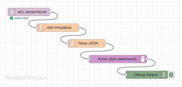
5) Description of the nodes:
- The first one is an MQTT subscriber node. Configure it to subscribe to your broker to get the data from the topic which the ESP8266 publishes on (this is acc_sensor/accel in the code above).
- The second and third nodes are JavaScript function nodes. They modify the received message to add a timestamp and parse the JSON. You can also combine this in one function node that has the following code:
msg.payload = {
    'data' : JSON.parse(msg.payload),
    'tstamp' : new Date().getTime()
};
return msg;
- The fourth node is the “IoT Datasource” node. It sends the message to a dashboard which we will create in the next step.
- You don’t have to include the debug node (last node).
Step 5: Quickly create a dashboard
The package node-red-contrib-graphs we installed in the previous step also comes with a dashboard for quickly generating graphs from live data.
Go to
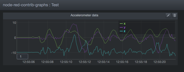
http://<your_node_red_host>:1880/dashand click on “Create new dashboard” in the top right. Give it a name (e.g. Test) and click Done. Click on “Create new chart”, also enter a name (e.g. “Accelerometer data”), and select the plugin “Line/Area Chart” from the dropdown menu.
Under “Datasources” you now select the datasource that you previously configured in your Node-RED flow. In my case, this is “Accel_data”. Click Done.
When you plug in your ESP8266 with the code from Step 2, you should now see an awesome live plot of the accelerometer measurements as they come in from the sensor. Awesome stuff!
Hi! So, you refer that data arrives at 10Hz intervals. What should I change if I want this frequency to be higher (let’s say 50Hz)?
Thanks in advance
Hi Manuel,
well, it is approximately 10Hz. There is always jitter in the network connection and other factors. But to change the actual sampling frequency of the sensor, you can change the line “IMU.setSrd(100)” to “IMU.setSrd(19)” in order to get a sampling rate of 50Hz. If you try it, maybe you can comment here again if the data actually arrives at 50Hz intervals? Would be nice!
Cheers
Nicolas
Hello Nicolas. This is exactly the project I need to build for work. I wonder: Do you do this using the ESP as the main chip that reads the sensor data? or do you use an arduino too?
In case of being the first option, which firmware should I use?
Hi Manuel, sorry for the late reply. I hope it is still helpful for you.
Yes, the ESP8266 is used for everything (network connection, MQTT publish, sensor initialization and reading), there is no extra Arduino involved.
There is no ready-made firmware, but you can use the code from the post above and change it as you like. Then you can compile it using PlatformIO and flash it onto the ESP8266.
Does this help you? If you have further questions, just let me know!