What parts do we need for this tutorial?
- ESP8266-based board (e.g. Wemos D1 mini)
- Accelerometer IC (e.g. MPU-9250, which is a 9-axis sensor)
- A breadboard
- Some jumperwires
Introduction
Welcome to this tutorial where we will explore reading measurements from an accelerometer sensor and displaying them on the serial console. An accelerometer is a device that detects acceleration along different axes (x, y, and z) by measuring the force of inertia on a small test mass. The measurements obtained from the sensor need to be converted to the unit m*s^2.
In this tutorial, we will be using an ESP8266 instead of an Arduino. The reason behind this choice is our ultimate goal of publishing the data to an MQTT broker. The ESP8266’s built-in WiFi functionality makes it ideal for this purpose. If you’re interested in setting up an MQTT broker, you can refer to our tutorial on setting up an MQTT broker here.
Step 0: Choose a sensor
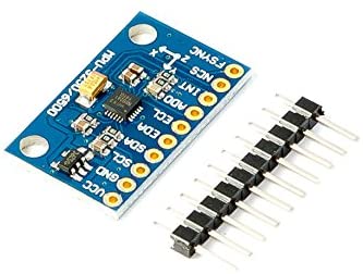
When it comes to accelerometer sensor ICs/boards, there are numerous options available in the market. For this tutorial, I have chosen the MPU-9250. This particular sensor is remarkable as it integrates multiple sensors into a single chip, allowing us to measure on a total of 9 axes:
- A 3-axis gyroscope
- A 3-axis accelerometer
- A 3-axis magnetometer (for measuring magnetic field strength)
For our current purposes, we will only utilize the accelerometer functionality.
To control the sensor, we have the choice of using either the SPI or I2C protocol. In this tutorial, we will be using SPI. However, we don’t need to handle all the low-level communication details ourselves. Thankfully, there are comprehensive libraries available that have already taken care of the underlying work for us.
Step 1: Prepare the board
We put the Wemos D1 mini and the MPU-9250 sensor on a breadboard, and connect the following pins:
- GND <–> GND
- VCC <–> 5V
- SCL <–> D5 (SPI clock pin) = Arduino pin 14
- SDA (slave data in) <–> D7 on Wemos (SPI MOSI pin) = Arduino pin 13
- ADO (slave data out) <–> D6 on Wemos (SPI MISO pin) = Arduino pin 12
- NCS (chip select) <–> D0 on Wemos = Arduino pin 16
- INT (interrupt notify) <–> D1 on Wemos = Arduino pin 5
Step 2: Setup the IDE
We will be using the Arduino IDE for this tutorial, although other IDEs like PlatformIO are also options. To begin, we need to clone the most recent version (6.0.3 at the time of writing, July 2nd, 2023) of the ‘Bolder Flight Systems MPU9250′ library by Brian Taylor from GitHub. If you’re interested, you can click ‘More Info’ to access the library’s GitHub page or simply click here.
Hint: If you use older versions (e.g. 5.6.0), there is an error with “eigen.h” which requires another library to be installed as mentioned in this issue here.
- Locate the Arduino libraries folder on your computer. How to do this can be found here.
- Open a Terminal and change to that library directory
- Clone the library from GitHub:
git clone --branch v6.0.3 https://github.com/bolderflight/invensense-imu
Step 3: Write the code
Fortunately, when writing the code I didn’t have to start from scratch as the library provides example code to help us get started. However, I highly recommend referring to the datasheet for the sensor and possibly exploring the library’s source code to gain a better understanding of how the microcontroller communicates with the sensor.
To ensure smooth program execution without delays, I have based my implementation on the library example which uses the “data ready” interrupt. By utilizing interrupts, the sensor notifies the microcontroller whenever a new measurement is available, eliminating the need for continuous polling of the sensor. This approach allows us to incorporate additional code into the same sketch later on without causing any blocking delays in the program execution.
We have made slight modifications to the example code, so please copy and paste the following code. You can also find the code in the GitHub Repository for this blog here.
#include "mpu9250.h"

/* Chip select is on pin 16 (Wemos D1 mini: D0) */
#define MPU9250_CS_PIN 16
/* Interrupt is on pin 0 (Wemos D1 mini: D1) */
#define MPU9250_INT_PIN digitalPinToInterrupt(5)

/* An MPU9250 object with the MPU-9250 sensor on SPI bus 0 */
bfs::Mpu9250 imu(&SPI, MPU9250_CS_PIN);

/* Keep track if interrupt is active */
volatile uint8_t irq_active = 0;
/* This is set in the ISR if new data is available */
volatile uint8_t new_data = 0;

void setup()
{
  /* Open the serial port, wait until ready */
  Serial.begin(115200);
  while (!Serial)
  {
  }

  SPI.begin();

  Serial.println("\n\nCalibrating...");

  /* Start communication with the IMU */
  if (!imu.Begin())
  {
    Serial.println("Error: IMU initialization unsuccessful. Check wiring.");
    Serial.print("Status: ");
    Serial.println(status);
    while (1)
    {
    }
  }

  /* Set bandwidth of the Digital Low Pass Filter to 20 Hz */
  bool status = imu.ConfigDlpfBandwidth(bfs::Mpu9250::DLPF_BANDWIDTH_20HZ);
  if (!status)
  {
    Serial.println("Error: Setting low pass filter value unsuccessful.");
    while (1)
    {
    }
  }

  /* Set the sample rate divider to 100 (results in 10 Hz update rate) */
  if (!imu.ConfigSrd(100))
  {
    Serial.println("Error: Setting sample rate unsuccessful.");
    while (1)
    {
    }
  }

  /* Enable the data ready interrupt */
  if (!imu.EnableDrdyInt())
  {
    Serial.println("Error: Activating interrupt failed.");
    while (1)
    {
    }
  }

  /* Attach the interrupt to microcontroller pin MPU9250_INT_PIN */
  pinMode(MPU9250_INT_PIN, INPUT);
  attachInterrupt(MPU9250_INT_PIN, isr_imu, FALLING);

  delay(500);
  Serial.println("\n\nInitialized MPU-9250! Let's go.");
  Serial.println("x\t\t y\t\t z");
  delay(500);

  irq_active = true;
}

void loop()
{
  if (new_data)
  {
    new_data = 0;

    /* Display the data (mps2 = meters per second squared (m/s^2) */
    Serial.print(imu.accel_x_mps2(), 6);
    Serial.print("\t");
    Serial.print(imu.accel_y_mps2(), 6);
    Serial.print("\t");
    Serial.print(imu.accel_z_mps2(), 6);
    Serial.println();
  }
}

ICACHE_RAM_ATTR void isr_imu()
{
  if (!irq_active)
  {
    return;
  }

  /* Read the sensor */
  if (imu.Read())
  {
    new_data = 1;
  }
}
Explanation
- Pin 16 is the Chip Select pin which corresponds to pin D0 on the Wemos D1 mini.
- The interrupt is attached to pin 0 (D1 on the board).
- We set the digital low pass filter to 20Hz. The Digital Low Pass Filter (DLPF) is a feature available in many IMU (Inertial Measurement Unit) sensors, including the MPU-9250. It helps to filter out high-frequency noise and unwanted vibrations from the sensor data, providing smoother and more reliable measurements.
- The sample rate divider is set so that we get a sample rate of 10Hz.
- Why do we need “ICACHE_RAM_ATTR”? The ESP8266 requires interrupt service routines to be stored in the correct memory area, specifically in the internal RAM and not the flash memory. On Arduino boards, this is not an issue, but the ESP8266 will crash with the error “ISR not in IRAM!” if we omit this hint.
- The interrupt only sets a status flag which tells us that there is new data. The data will then be read from the board in the main loop. We do this to avoid that the interrupt service routine takes too long to execute.
Step 3: Save, flash, run
Save the project to a new directory. Then, select the correct board (e.g. Wemos D1 mini) under Tools –> Board. If your board is not available, go to Tools –> Board –> Board Manager and install the correct package. If you are not sure what you should choose here or how to proceed, just write in the comments or contact me by email or social network, I will help you as soon as possible!
Also, under Tools –> Port select the correct USB serial device.
Now, click on the upload button. Your code will be compiled, flashed and then the board will be reset. Then, open the serial monitor (Tools –> Serial Monitor) and set the correct baudrate (115200).
If you get any error message, check that you have connected the wires correctly. Then reset the board.
Now you can watch the sensor data come in. Nice!

Ok .
1. careful with upper and lowercase. I had to make #include “MPU9250.h” #include “mpu9250.h”
2.More Border libraries need installing “eigen.h” and “units.h” as explained in the mpu9250.h readme.
3 Then trying to compile but all references to IMU seem faulty eg.C:\Users\USER\Documents\Arduino\wemos D1\wemos D1 1\wemos D1 1.ino:5:1: error: ‘MPU9250’ does not name a type
5 | MPU9250 IMU(SPI, MPU9250_CS_PIN);
So at this point I gave up. Some similar problems are explained on the web but seem to point at different library structures than my ver 2.04 has.
Hey Alan,
thanks for pointing that out. At the time I wrote the post, the code worked exactly as written above. Seems like the library has changed quite a lot in the last 2 – 3 years… Time to update the post. I have put it on my todo list 🙂
Edit: Post is now updated (July 2nd, 2023).